
Concrete construction is a common activity found on most jobsites throughout the world, one of the critical activities that goes into making sure that the concrete ends up where it needs to be is formwork. This Guide provides information on designing, erecting, using and dismantling formwork.
Table of Contents
What is the definition of formwork?
Formwork means the surface of the form and framing used to contain and shape wet concrete until it is self-supporting.
Formwork includes the forms on or within which the concrete is poured and the frames and bracing which provide stability. Although commonly referred to as part of the formwork assembly, the joists, bearers, bracing, foundations and footings are technically referred to as falsework.
Formwork construction may involve high risk activities like operating powered mobile plant like cranes, working at height and excavating foundations.
Safe work method statements (SWMS)
If the work involves high risk construction work, a SWMS must be developed in consultation with workers and their representatives who are carrying out the high risk construction work as defined under the Work Health and Safety (WHS) Regulations.
A safe work method statement is a document which outlines the steps in which a task needs to be performed and the hazards and controls necessary to help make the work safe.
Designing Formwork Systems
The design of the final concrete structure can have a major effect on the ease of formwork construction and the health and safety of people during construction. Generally the more basic and simple the final concrete structure, the safer it is to construct, erect and dismantle the formwork.
An experienced formwork designer should be consulted during the design of in-situ concrete structures to enable the health and safety risks during formwork construction and dismantling to be considered in the design.
The formwork designer must be competent in formwork design including documenting temporary work platforms and special equipment needed for safe formwork construction on-site.
A designer may use a technical standard or a combination of standards and engineering principles relevant to the design requirements as long as the outcome is a design that meets regulatory requirements.
Formwork should be:
- rigid, watertight, braced and tied together to maintain position and shape during construction , and
- able to be removed easily and safely without damaging the formed concrete, or have components that remain as part of the finished structure so the rest can be removed without damaging the structure.
Formwork drawings should include details of:
- formwork and formwork joints
- sealing procedures
- ties
- size and spacing of framing
- details of proprietary fittings or systems proposed to be used, and
- bond breakers, if used.
The formwork designer should determine the vertical pour rates for walls, columns and other vertical concrete elements before completing the formwork design.
Details of the construction method and erection sequence should be included on the formwork drawings where appropriate. Where special methods like external vibration are involved the formwork design should allow for any resulting additional structural loads.
Where formwork is to be re-used, the formwork design should ensure form strength is retained after allowing for the deterioration of materials through use, handling and storage.
All formwork drawings should be certified as complying with applicable laws. Components from different formwork systems should not be mixed unless a competent person, for example an engineer, has authorised the component use. Variations to a design of a system should be checked and verified in writing by a designer, engineer or other competent person.
Slips, Trips and Falls
The design of the permanent structure affects the risk of injury from slips trips and falls (and from falling objects) during formwork construction and use. While often not reasonably practicable, permanent structure design measures that can reduce these risks include:
- reducing variations in the floor depth so it has one consistent depth. Formwork decks that are a consistent depth are easier to erect than variable depth floors and minimise the risk of injury. Deeper beams introduce ‘drop downs’ into the floor, creating trip and fall hazards and require more work to construct and strip after pouring
- beams designed to provide suitable access across the beam recess to prevent injury to workers from stepping into the form during construction
- reducing the number of columns required and where columns do exist, eliminating capitals and dropdowns, and
- reducing cantilevered floor sections.
The design of formwork systems can also reduce the risk of slips trips and falls by providing adequate safe access and fall and falling object protection.
Manual tasks
The design of formwork systems can reduce the amount of manual handling required in formwork activity. To reduce manual handling risks use:
- precast columns and beams to minimise fixing reinforcement, erecting and stripping column formwork and pouring concrete on site – work activities carried out in a factory environment are generally lower risk
- table or flying forms—a large pre-assembled formwork and falsework unit often forming a complete bay of suspended floor slab, and
- modular formwork systems which are often lighter weight and eliminate the need for tasks like repetitive hammering.
Types of formwork in construction
The safety of workers erecting, using and dismantling the formwork should be considered when choosing a formwork system for a particular job. In particular consider stability, strength and the risk of falls, falling objects and manual tasks. The best proprietary systems have integrated safety features to help control the risk of falls and hazardous manual tasks.
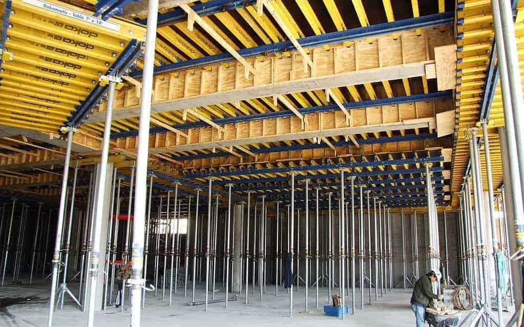
Traditional formwork systems (plywood formwork) are typically constructed on-site from timber or plywood and supporting elements like scaffolding.
When using a traditional system, a standard formwork frame with a known tested loading capacity should be used wherever possible. Standard frames can minimise the risk to workers erecting and dismantling the formwork and handling and storing materials.
Modular formwork systems (aluminum formwork / steel formwork) are specially designed and manufactured off-site. Modular systems usually have proprietary formwork components and rated load calculations set out by the manufacturer and are often made from hardboard, plastics, steel and aluminium products. Most formwork systems use two or more materials, for example plywood facing to steel frames for wall panels.
Modular systems are often lighter weight and require less physical effort than traditional systems. This minimises the risk of injury resulting from manual tasks. However because of their lighter weight, modular systems may be more susceptible to falling over when erecting the system due to factors like wind loading. Generally this will only be an issue before placement of the formwork deck on the modular system. To effectively control this issue the modular formwork system should be progressively braced in accordance with the suppliers instructions during its erection.

Formwork Systems – Wall and column forms
Wall and column forms should be designed to withstand wind loading before, during and after the concrete pour. The bracing and forms should not be removed from the cast element until it can safely withstand potential impact loads and wind loads.
Lateral support can be provided to vertical elements in a variety of ways including horizontal and angled braces and structural connections to other parts of the building. A bracing element design should be completed by a competent person.
The bracing element should also be able to resist both tensile and compressive loads that may be applied by the wind. Anchors for braces should preferably be cast-in type anchors or ‘through-bolts’ extending through both sides of the anchoring medium. Drill-in anchors of the following type may be used provided they are installed in accordance with the manufacturer’s instructions:
- Undercut type anchors that do not rely on friction to function.
- Expansion anchors of the high-load slip, torque controlled type. These anchors have a working load of at least 60 percent of the first slip load and are generally suitable for structural tensile loads.
- Coil bolts—the correct operation of coil bolts is greatly dependant on them being installed in accordance with the manufacturer’s specifications, for example drilling the correct size hole and applying the correct torque in concrete.
Note: Some jurisdictions may not accept these types of installations, so check with your WHS regulator.
Drill-in anchors should be installed in accordance with the manufacturer’s instructions.
They should have their torque set using a torque wrench or other reliable method to verify the torque, for example a calibrated ‘rattle gun’. Written records verifying the setting torque for drill-in type anchors should be available at the workplace.
Access platforms for wall and column formwork
Suitable access should be provided for wall and column forms and may include:
- mobile scaffolding
- purpose built access platforms, or
- elevating work platforms.
Edge protection should be provided on the access platforms. Preferred methods of entry to platforms include stair access systems or if this is not practicable secured industrial ladders.
The entry method should allow room for a person and be positioned at a height and distance from the form to minimise a person’s effort and movement. The concrete pouring system should permit enough space for a person to stand with edge protection provided. Where stair access passes a formwork deck, joist or bearers should not protrude over the stairs.
Platforms should also be designed to resist loading that may be applied during a concrete pour to ensure the platform does not collapse or overturn. They may need to be tied in or counter weighted, particularly aluminium scaffolding which may not have the self-weight to prevent overturning.
Mobile work platforms should have their castors locked, except when relocating the mobile platform.
Trailing access system
The designer should ensure a trailing access system can support the loads that will be applied to it including wind conditions and an emergency evacuation situation. Both the system itself and the form should be able to withstand applied loads from the access system.
Lifting methods for wall and column formwork
Wall and column forms should be provided with designed lifting points. Design drawings should confirm this. Cutting holes in the form in-situ is not recommended as this can damage the form, be inadequate lifting points and make it difficult to safely attach lifting gear.
Wall and column forms should only be lifted with a positive lifting system, for example lifting lugs or by slinging the lifting slings around the form so the form cannot slip out of the slings. Purpose designed lifting lugs should be used instead of slinging the load because there is less risk of the load becoming inadvertently disconnected from the crane hook.
Where lifting lugs are attached to the form they should be attached in accordance with the design.
Erecting formwork frames
Formwork frames should be erected progressively to ensure the installers’ safety and the stability of the overall structure.
Braces should be attached to the frames as soon as practicable and designated access ways should be indicated by using bunting or by other means.
If side bracing or other edge protection is installed progressively on formwork frames other control measures to prevent a fall occurring may not be required.
Many conventional formwork frames consist of diagonal braces that cross in the middle. While these braces are not considered to be suitable edge protection for a completed formwork deck, they may provide reasonable fall protection during frame erection. This is only the case where braces are installed in a progressive manner as soon as the frames are installed.
As the height of formwork frames increase there is a greater need to provide lateral stability to the frames. Ensure framing, including bracing, is carried out in accordance with on-site design documentation and manufacturers’ instructions. People erecting formwork must be trained to erect formwork using safe methods.
The risk of internal falls while erecting frames can be controlled by fully decking each lift of the formwork decks and false decks. This involves:
- positioning a full deck of scaffolding planks or other suitable decking at each lift
- positioning decking on the next lift while standing on a fully decked platform, and
- leaving each lift fully decked in place until it is dismantled.
During dismantling of a lift, decking should be removed while standing on a fully decked platform immediately below.
Formwork Systems – Suspended Slabs
Where the next formwork deck would require people to stand at heights of 2 metres or more above the finished formwork deck to install bearers and joists for the next formwork deck, a continuous ‘false’ deck, which is a full deck the same area as the floor being formed, should be provided.
This deck should be provided both inside and between formwork frames and typically consist of formply, scaffold planks or modular platform sections.
A protected entry opening can be left in the deck to enable materials to be lifted. Using a captive platform system is preferable to lapped planks because a captive system cannot be accidentally dislodged. Lapped planks may only be used if secured against uplift and slipping.
The false deck should be constructed so there are no large gaps and gaps only exist where a vertical member of a frame passes through the deck (see Figure 1). Gaps should not exceed 225 mm in width.

A false deck should be able to support the expected load of workers and materials during construction and people or objects that could fall onto the deck. Access should be provided to each of the false decks.
When considering the design of the deck for erecting, altering or dismantling formwork, the weight of the false deck and live load should be applied to the formwork support structure.
The height between the false deck and the pouring deck should allow entry for a person during stripping. Workers must take reasonable care for their own safety by not climbing the framework.
Intermediate platforms
Where the potential fall distance is less than 2 metres, an intermediate work platform can be provided that is at least 450 mm wide (see Figure 2).

Installing bearers
Bearers are the primary horizontal support members for a formwork deck that are placed on top of formwork frames. They are usually timber but are sometimes metal. They should be placed in position by people located on a secure platform no more than 2 metres below them.
Bearers should be positioned so they will not fall off the top of the frames. The usual method to do this is by placing the bearers in U-heads on top of the frames and by minimising cantilevers. U-heads should be used where two bearers abut. Where only single bearers are placed in the U-head, the bearer should be placed centrally in the U-head unless a formwork designer, engineer or other competent person states otherwise. This can be achieved by rotating the U-head or by using timber wedges.
Where the top of the supporting member consists of a flat plate, the bearer should be nailed or otherwise effectively secured to the plate. Flat plates should only be used where specified by a formwork designer, engineer or other competent person.
Installing joists to support formwork
Where a false deck is provided at 2 metres or less below a worker, joists may be spread on the bearers with the worker standing on top at bearer level.
If the height of the formwork deck being constructed is more than 2 metres above a continuous deck or surface below it, joists should be spread from a platform located within 2 metres of that surface, underneath the deck being constructed (see Figure 2). This work platform should be a false deck but an intermediate platform may be used.
A person should be provided with a working platform at least 450 mm wide (two planks) when the potential fall distance is less than 2 metres. It is not acceptable for a person to work from a single plank or bearer.
One example of a work system that may be used to do this is as follows:
- The joists are lifted by the workers from underneath and spread on top of the bearers into their approximate final positions whilst standing on a lower work platform.
- The platform below the deck should be positioned at a suitable height for handling joists without introducing manual task risks and not greater than 2 metres above the continuous deck or surface below.
Laying formply on the deck
A formwork deck should be laid in a progressive way so people will be provided with a method to prevent them from falling below the deck.
This control measure is particularly important in situations where a false deck has not been provided within 2 metres below the level of the deck to be laid. In this situation formply may only be spread on the joists provided:
- People start laying the formply sheets from the perimeter scaffolding or other edge protection provided on the perimeter of the formwork.
- A minimum of four joists at 450 mm centres—400 mm gaps, totalling 1.8 metres—are located on bearers next to the person and in the other direction joists extend for at least
1.8 metres (see Figure 3). Therefore, if a person falls they will fall onto the joists and should be prevented from falling further. In some situations, there may be a possibility of a person falling through the joists if the joists spread as the person’s body makes contact. This
is more likely to be a potential hazard when the person falls onto the joists in the same direction as the joists. Implementing controls to minimise sideways movement of joists will minimise this possibility.
- People lay the formply in front of their bodies so if they stumble they are likely to fall on top of the sheets being laid.
Where a leading edge is involved and the distance below the deck being constructed is greater than 2 metres the SWMS must detail how work will be completed to control the risk.

Cantilevers
Cantilevered bearers, joists and ply sheets can be hazardous when left unsecured. The weight of material or a person standing on the cantilever may make the timber see-saw and cause the person or material to fall. When designing the formwork system, the use of cantilevers should be kept to
a minimum. In some situations using cantilevered sections is unavoidable. In these cases, a formwork designer should consider the potential for people and stored materials to cause cantilevers to pivot.
Wherever the weight of a person will cause a cantilever to pivot, the formwork design should include
measures to secure the cantilevers so this will not occur. This may include temporary propping, nailing, bolting or another effective method. If nailing is used the formwork design should specify the nailing detail and this should be followed. This may include the use of purpose designed or proprietary brackets. Materials should not be stacked or stored on a cantilever section unless the section has been designed to carry the load. Temporary working platforms cantilevered from shoring frames are a form of cantilevered scaffold. Where a person or object could fall more than 4 metres from a scaffold, workers involved in erecting, altering or dismantling them must hold a scaffolding licence. The minimum licence class for this type of work is Intermediate Scaffolding.
Penetrations
Open penetrations like stairwells or penetrations to allow for services create hazards for people on the deck, for example a fall through a larger penetration, stepping into a smaller penetration or an object falling through the opening onto people below. A penetration where there is a risk a person or an object could fall through should be guarded.
Protect open penetrations with edge protection like handrails or by securely covering them so no one can fall through them. Penetrations in concrete slabs may include cast-in-mesh as a back-up system. The mesh should be of a small aperture, for example 50 x 50 mm mesh size or smaller and made of material capable of withstanding the potential imposed loads. Where mesh or other physical fall protection material is to be provided for larger penetrations this should be included in the slab design specifications to ensure it can withstand potential loads including those applied by people, equipment and material.
Where holes are cut in the mesh for services to pass through the hole should be cut to the profile of the service so the mesh remains in the penetration and the load carrying capacity of the mesh is not reduced below design specifications.
Using plywood covers alone is not a satisfactory risk control because:
- the cover may be indistinguishable from other pieces of plywood
- it cannot be refitted without significant modification, once the first service is installed
- it may be difficult to determine if the plywood is properly secured, and
- secured plywood covers can be unsecured to gain entry and not re-secured.
Plywood covers should be structurally graded, painted in a bright colour and marked with wording, for example ’Danger penetration below’. The cover should be firmly secured to the concrete and designed for potential loads that may be applied, for example workers, materials or plant that may travel over the cover.
Before stripping formwork, cover the penetration that will be exposed as the formwork is stripped or protect the penetration before starting the stripping operation.
Penetrations are also hazardous before the deck is laid. Joists placed up to the edge of the penetration should be secured so the timbers cannot spread if a person falls on them.
Working areas for steel fixers and others
Steel fixers, plumbers and electricians often follow closely behind the formwork erection. The formwork zone should be large enough to ensure these people are clearly separated from the form workers.
A ‘formwork only’ zone should be maintained behind the leading edge. This zone should be clearly marked by signs and a mesh barrier. Figure 4 shows the ‘other work’ zone, the ‘formwork’ zone and the area retained as edge protection—four joists spaced 1800 mm beyond the laid deck.

Temporary walkways laid across reinforcement mesh can be used to control the risk of slips and trips when multiple trades are entering large areas where reinforcement mesh has been laid behind formworkers.
A physical barrier should be provided and maintained to separate the formwork work zone from other workers. This barrier should be rigid, capable of maintaining its integrity in an upright position and capable of supporting signage if required.
Changing floor levels
Formwork decks are rarely flat across the entire floor, generally due to deep beams or ‘drop downs’ sometimes called ‘capitals’ around columns. Uneven floors introduce fall hazards.
These hazards are most effectively managed by ensuring formwork supports and the deck are progressively constructed for the lower parts of the deck before work starts on the higher- level areas of the deck.
Fall protection from the formwork deck
During formwork construction the structure is constantly changing so continual modification of fall protection measures is also necessary.
When there is only one leading edge where the other edges are provided with scaffold edge protection or safety screens, providing fall protection on the leading edge is relatively straightforward. However, where there are multiple leading edges or the deck is not at one consistent level, fall protection may be difficult to implement.
Edge protection on the formwork deck
Where the design of the formwork is complex, it may be impractical to provide edge protection on leading edges because the profile of the deck is constantly changing and constructing leading edge protection would create more hazards than it would control. For example, the people installing the edge protection could be exposed to risks when installing the edge protection.
In some situations it may be necessary to provide perimeter edge protection on edges of the formwork deck.
Examples where edge protection should be installed are:
- where there is a change in deck height along the side of the deck being constructed i.e. a drop down for a beam and no joists or formply has been provided at this different height
- when a leading edge is to be left unattended and entry onto the deck by people other than form workers is required i.e. the formwork deck has not been barricaded off and provided with ’keep out’ signs, and
- at openings in stairwells or lift shafts.
Perimeter containment screens or a scaffold are effective means of edge protection on a completed formwork deck. Scaffolding should be erected before the formwork and prevents workers falling off the completed deck. The main advantage of these systems is people
are not required to install edge protection on the perimeter of the formwork deck and are therefore not exposed to a risk of falling. The other advantage is edge protection for people installing the final perimeter formply sheets is already in place.
Where suspended, cantilevered, spur or hung scaffold, or any scaffold from which a person or object could fall more than 4 metres from the platform or the structure is used, any erection, alteration or dismantling of the scaffold must be carried out by licensed scaffolders. Cover gaps between a completed floor and scaffold after the formwork is stripped if there is a risk of a person or materials falling through the gap.
In some situations it may be impractical to provide perimeter containment screens or scaffolding. Use a work system to install perimeter edge protection on the deck which eliminates or minimises the risk of a fall.
Harness systems should not be used because they do not provide a practical control for the risk of a fall from height from the perimeter of formwork.
If required, edge protection can be substituted with an alternative measure provided this measure prevents a person falling from the edge. One alternative is providing a barricade
1.8 metres back from the edge with clearly visible warning signs.
Perimeter containment screens
Perimeter containment screens are protective structures fixed to the perimeter structure or working platform to prevent objects and people falling outside the work area. This significantly minimises the risk of injury to other workers and the public.
Screens should be used throughout the whole construction process especially while erecting or stripping formwork. They are usually sheeted with timber, plywood, metal or synthetic mesh.
Screens may be supported by the building or structure or by a specifically designed scaffold. The screens can also act as perimeter fall protection on a top working platform and should extend at least 2 metres above the working surface to provide protection for the public and workers outside the contained work area.
When selecting containment screens consider:
- the ability to support or contain imposed impact loads including building materials, equipment and waste materials
- resistance to wind loads on the supporting structure
- frequency of inspection
- chemical reactivity including flammability
- ventilation requirements
- light transmission requirements
- degree of protection provided from rain or washing down operations
- pattern and frequency of fixing points, and
- gaps created by a fixing method.
Containment screens should remain in position from the start of the formwork being erected until soffit stripping is complete to prevent objects falling throughout the process.
To prevent material from falling below, gaps between perimeter screens and the formwork deck or floor should not exceed 25 mm.
Removal of the formwork systems
Pre-loading inspection and certification of formwork systems
Inspection and certification processes each contribute to controlling risks during the construction of formwork and falsework.
Inspections and clearance to load should occur at key stages during the construction of formwork including when formwork is being loaded, for example with formwork components, equipment or pre stressed tendons and prior to its completion.
A separate certification process should occur when the formwork is complete and prior to concrete being poured.
A competent person such as an engineer with experience in structural design (certifying engineer) should inspect and certify that completed formwork meets the design specifications and is structurally sound before it is loaded. Generally certification will not be required for formwork and falsework in housing construction work.
The certifying engineer should complete and provide a Formwork Structural Certificate
to the person with management or control of the formwork, often the principal contractor. An example is at Appendix A.
Where a scaffold is being used there are specific requirements to control entry to the scaffold and for inspection and certification prior to use.
Loading Formwork Systems
The formwork should not be subjected to a load until it is confirmed as meeting the design specification, for example by completing a pre-pour inspection before placing concrete.
Loads should not exceed the design loading specified by the designer.
To maintain stability of the forms the placement of concrete should not exceed the maximum calculated pour rate and the inboard part of formwork should be placed before proceeding to any cantilever section.
Hoisting, pumping and other equipment should not be attached to the formwork unless specifically allowed for in the formwork design.
Formwork should be monitored as it is loaded to check for indications of potential failure or collapse and that vertical and horizontal movements do not exceed specifications.
Monitoring And Inspection of Formwork Systems
A competent designated observer should continuously monitor the formwork assembly during concrete placing operations and be provided with an appropriate communication system to alert others in case an emergency arises.
Other than a designated observer, no person should be underneath a formwork deck during concrete placement. An observer should not stand directly underneath an area where wet concrete is being placed into the forms.
Competent persons should be available during concrete placement to carry out any emergency adjustments or repairs. The concrete placement should cease during adjustments and repairs.
Pre-stripping certifications for formwork
Once the concrete is cured and before starting the stripping operation a competent person, for example an engineer with experience in structural design should provide written confirmation the permanent structure is self-supporting and the formwork can be removed. The certification should be based on the design specifications for the structure, the verification of the strength of the concrete mix and the time period elapsed since the pour.
Documentation from the concrete supplier verifying the concrete specification should be available on request. A concrete sampling and testing procedure should be in place to verify the concrete meets its design specification.
A competent person should also provide input into the SWMS on formwork stripping to ensure the permanent concrete element will not fail and result in structural collapse.
Stripping formwork
As with formwork erection, the stripping operation should be carried out in an orderly, systematic and progressive manner, considering the risks of falls, falling objects and manual task hazards in the now enclosed space.
When assessing the risks from stripping formwork consider:
- the number of people in the stripping crew
- the sequence of stripping activities – this should detail how the frames and other supports should be removed i.e. how far U-heads are to be lowered
- whether the support system will be completely removed in a zone before removing the formwork deck or whether the supports will be lowered slightly but remain under the formply while it is being removed
- removing nails and sharp fixings before stacking the components
- minimising damage to the components
- stacking the formwork components—do not obstruct access ways or work areas
- formwork components are not dropped or thrown from a building or structure
- flatheads are not supporting the ends of bearers
- when back-propping is required or only part of the support system is to be removed, how the structural members will remain in place and the type and layout of members that will replace the formwork system
- other special requirements involved in the stripping and or building process e.g. checking of back-propping after post-tensioning
- providing lighting for the work area and surroundings, and
- maintaining housekeeping, removing nails and rejected materials, stacking stripped formwork and removing tripping hazards e.g. concrete nails and brace anchor inserts from the floor.
Formwork removal should be carried out in a systematic way so the deck is gradually removed as the support system. Formply may be removed by partially lowering the support system and then dropping the segment of the deck (sheet) onto the support system. This eliminates the need to manually lift sheets of ply from ground level.
Bond reduction
Stripping formwork is easier when the strength of the bond between the form material and the concrete is reduced. The bond will be dependent on the material characteristics and the smoothness of the form material. A liquid bond breaker can be used on wall and column forms to reduce the strength of the bond but use on floor forms is not encouraged because it can cause a slip hazard.
Drop stripping
‘Drop stripping’ describes the method used when all of the formwork support system is removed and the formply is then allowed to drop to the level below either by its own weight or by people levering it off.
Drop stripping should not be used. It can be very hazardous because the formply is likely to fall uncontrolled and can hit people in the vicinity of the work.
Interesting perspective .Your analysis of the economic trends is quite insightful. I particularly appreciate how you’ve delved into the various factors influencing market dynamics, such as consumer behavior and global trade policies.Thanks for sharing, Proact, founded in 2001 and based in Bengaluru, is a leading force in high-tech industries like aerospace, aviation, electronics, defense, and more. Renowned for innovation and excellence, Proact offers tailored solutions to diverse challenges, making it a trusted partner for businesses. Explore cutting-edge services and products at https://www.proact-ims.com/ or contact us at +91 80 3542 9949 for collaboration and innovation opportunities. Elevate your projects with Proact’s expertise.
By following these practices, construction professionals can enhance the efficiency, safety, and quality of their projects, ensuring that formwork contributes positively to the overall success of the construction process.Explore our services at https://www.proact-ims.com/ or contact us at +91 80 3542 9949 for collaboration opportunities. Elevate your network capabilities with Proact’s expertise.