


Formwork (also called shuttering) is the temporary or permanent mould that holds fresh concrete in shape until it is strong enough to support itself. It includes the contact face, called sheathing, plus the studs, walers, ties and bracing that hold it in position. The supports under slabs and beams are usually called falsework or shoring.
This guide is for superintendents, foremen, project engineers and estimators who build or manage cast-in-place concrete. It compares the main formwork systems, explains the loads formwork is designed for, gives you a pre-pour checklist, and shows how to decide when forms can come off safely under US and Canadian rules.
Key takeaways
- Formwork shapes the concrete; falsework and shores hold it up. Reshores carry the load after stripping.
- Fresh concrete pushes sideways like a liquid. Pour rate, temperature and mix control how hard, so the design pour rate is a limit, not a suggestion.
- ACI 347 is the main North American formwork guide. The formwork engineer designs the forms; the engineer of record (EOR) sets the strength needed before stripping.
- Strip by verified strength, not the calendar.
- OSHA 29 CFR 1926 Subpart Q requires formwork designed for all loads, drawings on site, shores inspected and forms left until the concrete can carry its load.
Editable template
Get the Formwork / Shuttering Quality Checklist
An editable inspection checklist for formwork and shuttering, so your crew checks the same items before every pour without building a form from scratch.
What is formwork in construction?
Every cast-in-place element, from a footing to a high-rise core, needs a mould while the concrete hardens. Good formwork has four qualities:
- Strength to carry wet concrete, rebar, workers and equipment.
- Stiffness so it does not bulge or sag out of tolerance.
- Tightness so paste does not leak and leave honeycombing.
- Strippability: it comes off safely without damaging the concrete, unless it is designed to stay in place.
“Shuttering” is the usual term in the UK and India. North Americans say “forms” or “formwork”, and in MasterFormat it sits in Section 03 11 00, Concrete Forming.
Types of formwork compared
The right system depends on reuse count, how repetitive the structure is, crane access and the specified finish. Most systems combine materials, such as plywood faces on aluminium frames. Reuse figures are typical ranges; they depend on handling and care, so check supplier data.
| Type | Main materials | Typical reuses | Cost level | Best use |
|---|---|---|---|---|
| Timber | Dimensional lumber, boards | Few | Low material, high labour | Footings, small jobs, odd shapes, infills |
| Plywood | Plyform or MDO/HDO overlaid plywood on timber | About 5–10; more with overlaid faces | Low–medium | Low-rise walls, slabs, beams, custom shapes |
| Steel | Steel panels and frames | Very high (often 100+) | High to buy, low per use | Columns, repetitive walls, civil work, smooth finishes |
| Aluminium | Aluminium frames, ply or aluminium face | High (often 100+) | High (buy or rent) | Hand-set wall and slab systems, repetitive towers |
| Plastic | ABS, polypropylene or composite panels | Medium–high | Medium | Light walls, columns, repetitive housing |
| Fabric | Geotextile or membranes | Usually single use | Low | Pile jackets, underwater work, curved shapes |
| Stay-in-place / ICF | Insulated concrete forms, steel deck, permanent liners | None; stays in place | Medium, no stripping | Insulated walls; composite slabs on steel deck |
| Slipform | Steel forms on hydraulic jacks | Continuous, one setup | High setup | Cores, silos, towers with constant section |
| Jump / climbing | Crane- or self-climbing steel or aluminium systems | Many cycles | High | High-rise cores, shafts, tall walls in lifts |
| Table / flying | Pre-assembled deck and falsework units | Many floor cycles | Medium–high | Repetitive flat-plate slabs |
| Tunnel | Steel half-tunnel units | Very high | High | Repetitive cellular buildings (apartments, hotels) |
Traditional vs system formwork
Traditional formwork is built on site from lumber and plywood. It is flexible and cheap to start but labour-heavy. Support it on standard shoring frames with tested load ratings, not improvised posts.
System (modular) formwork is manufactured with rated components and load tables. It is lighter, faster and more consistent. However, light panels and frames can blow over before they are braced or loaded, so brace them progressively. Never mix components from different systems without written engineering approval.

Formwork by element
- Footings: job-built timber or steel edge forms, or earth-formed where the spec allows.
- Walls: two faces tied together and braced. Crane-handled gang forms suit long, repetitive walls.
- Columns: tube forms for round columns, adjustable panel or plywood box forms for square ones. They fill fast, so pressure runs high.
- Slabs and beams: a deck on joists and stringers carried by shores, or table forms on repetitive floors.
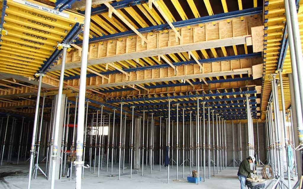
If you fly tables, use the Formwork Table Pre-Flying Construction Checklist to check rigging, loose material and the drop zone before each lift. For the crane side, see our guide to construction tower cranes.
How to choose a formwork system
Work through these questions with your formwork supplier or engineer before you price the job:
- How many reuses? Count identical pours. A few uses favour job-built plywood; dozens favour aluminium, steel or table systems.
- How repetitive is the geometry? Constant wall thicknesses, column sizes and slab depths let a system cycle. Odd shapes and one-offs suit timber.
- What lifting is available? Gang forms, tables and jump forms need crane time; hand-set aluminium panels don’t.
- What finish is specified? Architectural concrete needs tight joints, quality faces and often a mockup; buried footings don’t.
- What is the schedule? Cycle time per floor or per lift often decides the system more than material cost.
- What can your crew build safely? Unfamiliar systems need supplier training and engineering support on site.
Formwork vs falsework vs shoring and reshoring
These terms are used loosely on site, which causes real trouble when someone strips the wrong thing. Typical usage:
| Term | What it is | What it does |
|---|---|---|
| Formwork | Sheathing and its framing (studs, walers, joists) | Shapes the concrete and resists its liquid pressure |
| Falsework | Temporary structure under the forms: shores, frames, stringers, bracing, mudsills | Carries vertical and lateral loads to the ground or structure below |
| Shoring | Vertical supports (posts, props, frames); often used to mean falsework in the US | Holds up the slab or beam during the pour and early curing |
| Reshoring | Shores installed after the original forms and shores are removed | Shares load from fresh floors above with slabs below |
| Backshoring (back-propping) | Shores placed snugly as small areas are stripped, so the slab does not deflect | Same purpose as reshoring, with less deflection |
On multistorey work, a fresh slab is carried through shores and reshores down several floors that may not yet be at full strength. That load path must be engineered; ACI 347.2R, ACI’s guide to shoring and reshoring of concrete multistory buildings, is the usual reference. See also our glossary entry on shoring.
Formwork design: the loads in plain terms
Formwork fails like any structure: suddenly, and usually mid-pour. The main US reference is ACI 347, Guide to Formwork for Concrete, from the American Concrete Institute. In Canada, CSA S269.1 covers falsework and formwork, and CSA A23.1 covers concrete construction. This section helps you read formwork drawings and ask the right questions. It does not replace a design by a qualified formwork engineer.
1. Lateral pressure of fresh concrete
Wet concrete acts like a heavy liquid. The worst case is full liquid head: unit weight times the depth of fluid concrete above the point checked. Normal-weight concrete is about 150 lb/ft³ (roughly 23.5 kN/m³).
Worked example (illustrative): a 12 ft wall filled before any concrete stiffens sees about 150 × 12 = 1,800 lb/ft² at the base. That load runs through the plywood, studs and walers into the ties, which is why ties are closer together near the bottom.
As concrete starts to set, the lower part pushes less. ACI 347 gives reduced-pressure formulas for walls and columns, but only within limits on mix, slump, placement and vibration. For most self-consolidating concrete (SCC), pumping from the bottom of the form or external vibration, designers typically use full liquid head.
2. Rate of placement
Rate of placement is how fast concrete rises in the form, in feet per hour. It is the variable the field controls, and the one most often exceeded.
Worked example (illustrative): a wall 40 ft long and 12 in thick has 40 ft² of plan area. A pump delivering 20 yd³/h (540 ft³/h) raises it 540 ÷ 40 = 13.5 ft/h. If the forms were designed for 5 ft/h, the crew must place in layers along the wall. Columns fill even faster. Put the design rate on the drawings, brief it before the pour and track it during placement.
3. Temperature and mix design
Cold concrete stays fluid longer and pushes harder. Retarders, slag and fly ash have a similar effect. A form that was fine in July can be overloaded at the same rate in November, so tell the formwork engineer about any change in mix or weather. See our guide to working with concrete in cold weather for its other effects, including slower strength gain.
4. Vertical and lateral loads on slab forms
Slab forms carry dead load (concrete, rebar, forms) plus construction live load. An 8 in normal-weight slab alone is about 100 lb/ft². ACI 347 sets minimum live loads, which are higher where motorized buggies are used, and a minimum horizontal load on shoring for pump surge, wind and uneven placement. Check the current edition for exact values. Common failures are heaped concrete overloading one bay and shoring with no lateral bracing.
Who designs formwork?
Formwork is usually the contractor’s responsibility. It is designed by a formwork engineer working for the contractor or the supplier, and many jurisdictions and specs require a PE (US) or P.Eng. (Canada) seal above set heights or loads. The engineer of record typically reviews formwork and reshoring submittals only for their effect on the permanent structure, and sets the concrete strength needed before stripping and reshoring. Your Section 03 11 00 spec defines the split.
What formwork drawings should show
- Panel layout, joints and joint sealing
- Tie type, capacity and spacing
- Size and spacing of sheathing, studs, walers, joists and stringers
- Shore type, capacity, spacing, bracing and mudsills
- Design pour rate, concrete temperature and mix assumptions
- Erection, stripping and reshoring sequence
- Proprietary components with supplier load data
- Access platforms, edge protection and lifting points
OSHA 1926.703(a)(2) requires drawings for formwork, shoring, working decks and scaffolds, including all revisions, to be available at the jobsite. Get the designer’s written approval before making any field change.
Tip: the permanent design drives formwork cost and safety. Consistent slab depths, fewer drop beams and capitals, repeated column sizes and fewer cantilevers mean simpler decks, fewer fall hazards and more reuse. Bring a formwork contractor into preconstruction early.
Formwork components and what each one does
| Component | Function | What to check |
|---|---|---|
| Sheathing (plywood, Plyform, MDO/HDO, metal face) | Contact surface that shapes and finishes the concrete | Grade and thickness, face condition, tight joints, release agent |
| Studs | Back up the sheathing on walls and columns | Spacing per design, no splits |
| Walers | Horizontal members tying studs together and taking the ties | Doubled where shown, spliced correctly |
| Strongbacks | Vertical stiffeners over walers for alignment | Plumb, fixed at each waler |
| Form ties (snap, taper, she-bolt, coil) | Hold opposite wall faces against concrete pressure | Rated type, spacing, all installed and tight |
| Joists | Support the slab deck | Spacing, span, splices only over supports |
| Stringers (bearers in UK/Australia) | Carry joists to the shores | Centred in U-heads, short cantilevers |
| Shores, props, frames | Carry vertical load down | Plumb, rated, braced, jacks within extension limits |
| U-heads, screw jacks, base plates | Adjust height and seat members | Full bearing, locked where required |
| Mudsills | Spread shore loads onto ground or slab | Firm, level, protected from washout and frost |
| Bracing and kickers | Resist lateral load, hold forms plumb | Installed as erection proceeds |
| Accessories (chamfers, bulkheads, keyways, waterstops, blockouts, embeds) | Edges, joints, openings, cast-in items | Located per drawings, secured against floating |
Erecting formwork safely, step by step
These steps follow a typical suspended slab on shoring frames. The figures come from Australian guidance and use metric dimensions. In the US, fall protection is required at 6 ft (about 1.8 m) under OSHA Subpart M; Canadian provinces set their own heights.
- Prepare the base. Set mudsills on firm, level ground, or confirm the capacity of the slab below.
- Erect and brace frames progressively. Cross-braces installed as you go give some protection during erection, but they are not edge protection for a finished deck.
- Deck every lift. Install a full false deck inside and between frames, with gaps only at frame legs (Figure 1). Place the next lift’s decking while standing on a fully decked platform below.
- Use intermediate platforms at least two planks wide where the false deck is too far below the work. Never work from a single plank or a stringer (Figure 2).
- Seat stringers in U-heads, centred, with U-heads at butt joints and cantilevers secured against tipping.
- Spread joists from the platform below, not standing on the stringers.
- Lay sheathing from protected edges, placing sheets in front of you over closely spaced joists so a stumble lands on timber (Figure 3).
- Separate trades. Keep a marked “formwork only” zone behind the leading edge with a rigid barrier (Figure 4).
- Form low areas first, such as drop beams, so nobody works beside an open drop.
- Guard penetrations immediately. Under OSHA 1926.502(i), covers must support twice the expected load, be secured and be marked “HOLE” or “COVER”.


Wall and column forms: bracing, lifting and access
- Brace for wind before, during and after the pour, with braces that work in tension and compression.
- Anchor braces with cast-in anchors or through-bolts where possible. Drill-in anchors must be the specified type, torqued with a calibrated tool, with the torque recorded.
- Lift only from designed lifting points, never from holes cut in the field.
- Provide guarded access platforms, reached by stairs or secured ladders, designed for pour loads and secured against tipping.
Many contractors issue a permit before forming starts, confirming drawings, crew competence and access. The Work Permit – Concrete Formwork template sets that up quickly.
Pre-pour formwork inspection checklist
OSHA 1926.703(b) requires erected shoring to be inspected immediately before, during and after placement. Most specs also require a documented pre-pour sign-off, often by the formwork engineer or their delegate on engineered falsework. Start with these items:
Geometry and finish
- Lines, levels, dimensions and plumb within ACI 117 or spec tolerances; camber set
- Forms clean of debris, ice and water; release agent applied, kept off rebar
- Joints sealed; chamfers and liners secured
- Screed rails set for the specified flatness (see Concrete Slab Finishes and the F-System Explained)
Structure and supports
- All ties installed and tight, including at corners and bulkheads
- Walers, strongbacks and braces complete
- Shores plumb, correctly spaced, fully seated, jacks within limits, on sound mudsills
- Lateral bracing complete; reshores in place below per the plan
Embeds, rebar and pour readiness
- Rebar inspected with cover maintained; embeds, sleeves and blockouts secured
- MEP trades and any special inspector or authority having jurisdiction (AHJ) signed off
- Design pour rate briefed to the placing crew and pump operator
- Form watcher assigned, with authority to stop the pour
- Nobody under the deck during placement except the watcher, who stays clear of the area being poured
- Carpenters, wedges and spare shores on hand
- Guardrails, hole covers and rebar caps in place; weather within design assumptions
Editable template
Get the Concrete Pre-Pour Checklist Template
An editable pre-pour checklist that records formwork, rebar, embeds and trade sign-offs in one place, so you release every pour with a clear paper trail.
For walls and columns, use the Concrete Pre-Pour Checklist (Verticals). To book the pour, use a Request for Concrete Pouring form or a Concrete Pouring Permit, so no concrete is ordered until the forms are signed off. See Controlling Quality on the Construction Site for the wider process.
Formwork stripping times: when can forms come off?
No single number of days fits every job. Under OSHA 1926.703(e), forms and shores stay until the employer determines the concrete can support its own weight and superimposed loads. That determination must be based on the plans and specs, or on proper testing with an appropriate ASTM method. Your specs, the EOR and ACI 347 (and CSA A23.1 in Canada) govern; the guidance below is typical practice only.
- Vertical forms (walls, columns, beam sides, footings) do not carry the element’s weight. They usually come off once the concrete holds its shape and the surface won’t be damaged, often the next day in mild weather. Cold weather, retarded mixes and architectural finishes push this out, and curing must start as soon as the faces are exposed.
- Slab and beam soffits and their shores carry the full weight plus construction loads. They stay until the concrete reaches the strength the EOR specifies, usually a psi or MPa value or a percentage of f′c, as confirmed by tests. Reshores usually follow.
How strength is verified
- Field-cured cylinders made and cured beside the element (ASTM C31) and tested under ASTM C39. Lab-cured cylinders reflect the mix, not the slab.
- The maturity method (ASTM C1074), which uses embedded temperature sensors and a mix-specific calibration to estimate in-place strength.
- Cast-in-place cylinders (ASTM C873) or other in-place tests, where the specs allow.
| Factor | Effect on stripping |
|---|---|
| Temperature | Cold slows strength gain sharply; heat speeds it up but raises curing risks |
| Cement and supplementary materials | High-early cement speeds it up; high fly ash or slag usually slows early strength |
| Admixtures | Accelerators speed it up; retarders slow it down |
| Span and element | Long spans and cantilevers need more strength and reshoring |
| Loads above | Fresh floors, materials or equipment raise the required strength |
| Post-tensioning | Soffits usually stay until tendons are stressed per the PT sequence |
Day-based stripping tables still appear in textbooks and in codes outside North America, and they are what most online answers quote. The best-known is the table in India’s IS 456:2000, reproduced below for ordinary Portland cement at normal temperatures. Use it as background only. On a North American job, your spec, test results and the engineer’s written release govern.
| Formwork (IS 456:2000, Clause 11.3.1) | Minimum period before striking |
|---|---|
| Vertical formwork to columns, walls and beams | 16 to 24 hours |
| Soffit formwork to slabs (props refixed immediately after removal) | 3 days |
| Soffit formwork to beams (props refixed immediately after removal) | 7 days |
| Props to slabs spanning up to 4.5 m (about 15 ft) | 7 days |
| Props to slabs spanning over 4.5 m | 14 days |
| Props to beams and arches spanning up to 6 m (about 20 ft) | 14 days |
| Props to beams and arches spanning over 6 m | 21 days |
How to strip formwork safely
- Get written release from the engineer or competent person, based on the specs, verified strength and time since the pour.
- Plan the sequence: crew size, order of lowering, how far U-heads drop and where reshores go.
- Cover penetrations that stripping will expose.
- Strip progressively. Lower supports slightly so each sheet drops a short distance onto them, rather than pulling sheets down overhead.
- Never drop-strip, which means removing all supports and letting the deck fall or prising it off. The sheets fall uncontrolled.
- Reshore each bay as soon as it is stripped.
- Keep housekeeping tight. Pull nails, stack components clear of access ways, light the area and never throw material off the building.
Release agent on wall and column forms makes stripping easier. Use it sparingly on decks, where overspray is a slip hazard.
Formwork safety: OSHA Subpart Q and beyond
OSHA 29 CFR 1926 Subpart Q (1926.700 to 1926.706) covers concrete and masonry construction. In general terms it requires:
- Formwork designed, erected, braced and maintained to support all vertical and lateral loads (1926.703), with drawings and revisions on site.
- Shoring inspected before use and before, during and after the pour; damaged shoring removed from service.
- Forms, shores and reshores left until the concrete has enough strength.
- No construction loads on a structure until a qualified person confirms it can carry them (1926.701(a)).
- Protruding rebar guarded against impalement (1926.701(b)).
- No workers behind post-tensioning jacks, and nobody riding concrete buckets.
Subpart M (fall protection, including workers on the face of formwork or rebar at 6 ft or more), Subpart L (scaffolds) and Subpart CC (cranes) also apply. For the basics, see The Basics of Fall Protection.
In Canada, provincial occupational health and safety regulations apply, along with CSA S269.1. Many provinces require sealed engineered drawings for falsework above set heights or loads, and fall protection heights vary. Check your province’s rules and the engineer of record.
Practical controls: erect perimeter scaffold or containment screens before the deck and keep them until soffit stripping is done. Barricade unattended leading edges. Control the drop zone during erection, pours and stripping. Train crews on the specific system, keep a competent person on site, and brief each activity in a job hazard analysis (JHA) or pre-task plan, which Australian sites call a safe work method statement (SWMS).
Formwork cost and reuse tips
Formwork is often one of the largest cost items in a cast-in-place frame, and most of that cost is labour, not material. To cut it:
- Design for repetition: standard column sizes, wall thicknesses and slab depths.
- Choose the system by reuse count. Job-built plywood wins for a few uses, and systems win over many cycles. Ask suppliers for cost per use, not just rental rates.
- Plan the cycle so forms go straight from strip to the next set without double handling.
- Look after the faces: clean, re-oil and store flat off the ground right after stripping.
- Estimate and track by contact area (ft² or m² of form touching concrete), measuring labour-hours per unit with a Horizontal Formwork Productivity Monitoring Form.
Common formwork mistakes
- Pouring faster than the design rate, the classic cause of blowouts
- Changing the mix or pouring in cold weather without telling the formwork engineer
- Missing or wrong ties at corners, bulkheads and pour breaks
- Shores on soft or frozen ground, or screw jacks over-extended
- No lateral bracing on shoring
- Mixing system components or making unapproved field changes
- Stripping by the calendar, or forgetting reshores
- Drop stripping, or throwing material off the building
- Unmarked plywood hole covers that get removed and not replaced
- No form watcher, or people working under the deck during the pour
Frequently asked questions
Why is formwork used?
To hold fresh concrete in the required shape, position and finish until it can support itself. It also gives workers a platform for placing rebar and concrete, and it largely determines surface finish, accuracy and the speed of the job.
What are the main types of formwork?
By material: timber, plywood, steel, aluminium, plastic and fabric. By system: job-built, modular panel, stay-in-place (such as ICF), slip, jump or climbing, table or flying, and tunnel forms. Most projects mix them by element, reuse count and finish.
Is shuttering the same as formwork?
In practice, yes. “Shuttering” is the common term in the UK and India. Some people use it for the face material only and “formwork” for the whole assembly. North American specs say “formwork” or “concrete forming”.
What is the difference between formwork and falsework?
Formwork is the mould that shapes the concrete. Falsework is the temporary structure (shores, frames, stringers, bracing) that holds the formwork and wet concrete up until the permanent structure can carry itself.
How long before you can remove formwork?
It depends on the element, mix, temperature and loads. Vertical forms often come off the next day in mild weather. Soffits stay until tests show the strength the engineer of record specifies. Follow your specs, the EOR and ACI 347, not a fixed number of days.
Who is responsible for formwork design?
Usually the contractor, through a formwork engineer or the supplier’s engineering team, often with a licensed engineer’s seal. The engineer of record reviews submittals for their effect on the structure and sets stripping and reshoring strengths.
Which wood is used for formwork?
In North America, most form faces are plywood made for concrete forming, such as APA Plyform (usually Class I or Class II, often mill-oiled) or overlaid MDO and HDO panels for smoother finishes and more reuses. Framing is typically dimensional lumber such as Douglas fir-larch, hem-fir or spruce-pine-fir, or engineered timber beams in system formwork. Check the supplier’s span and pressure tables for the grade you use.
What is slipform construction?
Slipforming is a continuous process where a short form, typically about 3 to 5 ft (1 to 1.5 m) tall, is jacked upward while concrete is placed, so the wall is formed without stopping. It suits cores, silos, chimneys and towers with a constant or gently changing section, and usually runs around the clock until the top is reached. Horizontal slipform machines use the same idea for curbs, barriers and paving.
What is a false deck in formwork?
A full working platform installed inside and between shoring frames below the deck being built. It limits fall distance while workers place stringers and joists, and it catches dropped materials.
What is the best formwork system?
There isn’t one. Job-built plywood suits a few uses and odd shapes. Aluminium or steel systems and table forms pay off on repetitive work. Tall cores suit jump or slipforms, and cellular buildings suit tunnel forms. Compare cost per use, labour, crane time and finish.
Summary
Formwork is temporary, but it is a real structure. It has to be designed, built to drawings, inspected and removed in a planned order. Choose the system by reuse, respect the design pour rate, inspect before and during every pour, and strip only on verified strength and written release. Back each step with a simple paper trail: permit, pre-pour checklist, pour request and stripping release.
Every template you need for this, in one membership
Members get the formwork permits, pre-pour checklists and pour request forms used throughout this guide, ready to edit for their next concrete job. Get unlimited access to 1,200+ editable construction templates, forms and checklists.
- Quality Assurance Checklist – Formwork / Shuttering
- Concrete Pre-Pour Checklist Template
- Work Permit – Concrete Formwork
This guide is general information. Rules for contracts, payment and site safety differ by country, state and province. Check your contract and local regulations, and get professional advice where it matters.
Ask AI about this page: ChatGPT, Claude or PerplexityCopy as Markdown
Interesting perspective .Your analysis of the economic trends is quite insightful. I particularly appreciate how you’ve delved into the various factors influencing market dynamics, such as consumer behavior and global trade policies.Thanks for sharing, Proact, founded in 2001 and based in Bengaluru, is a leading force in high-tech industries like aerospace, aviation, electronics, defense, and more. Renowned for innovation and excellence, Proact offers tailored solutions to diverse challenges, making it a trusted partner for businesses. Explore cutting-edge services and products at https://www.proact-ims.com/ or contact us at +91 80 3542 9949 for collaboration and innovation opportunities. Elevate your projects with Proact’s expertise.
By following these practices, construction professionals can enhance the efficiency, safety, and quality of their projects, ensuring that formwork contributes positively to the overall success of the construction process.Explore our services at https://www.proact-ims.com/ or contact us at +91 80 3542 9949 for collaboration opportunities. Elevate your network capabilities with Proact’s expertise.